(1) A TD-LTE Baseband Unit
In 2009, I joined the Wuhan National Laboratory for Optoelectronics as a master student, as well as an R&D engineer. I was involved in a huge national project called “Comprehensive Testing Platform for TD-LTE Systems”, which received around $ 2,000,000 of budget.
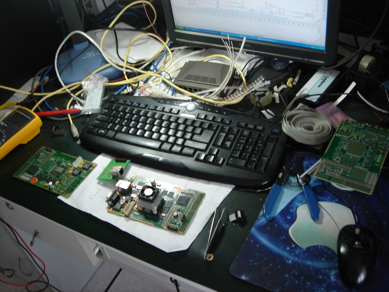
From Oct. 2009 to Jul. 2010, I was in charge of the hardware development for the LTE baseband system. My design target was to build a TD-LTE baseband board supporting 3GPP Release 8 with 20MHz of transmission bandwidth. Fig. 1 and Fig. 2 below is the hardware I implemented.


Some features of this board
• CPU: MPC8560, a PowerPC™ processor with 1.8 GHz of clock
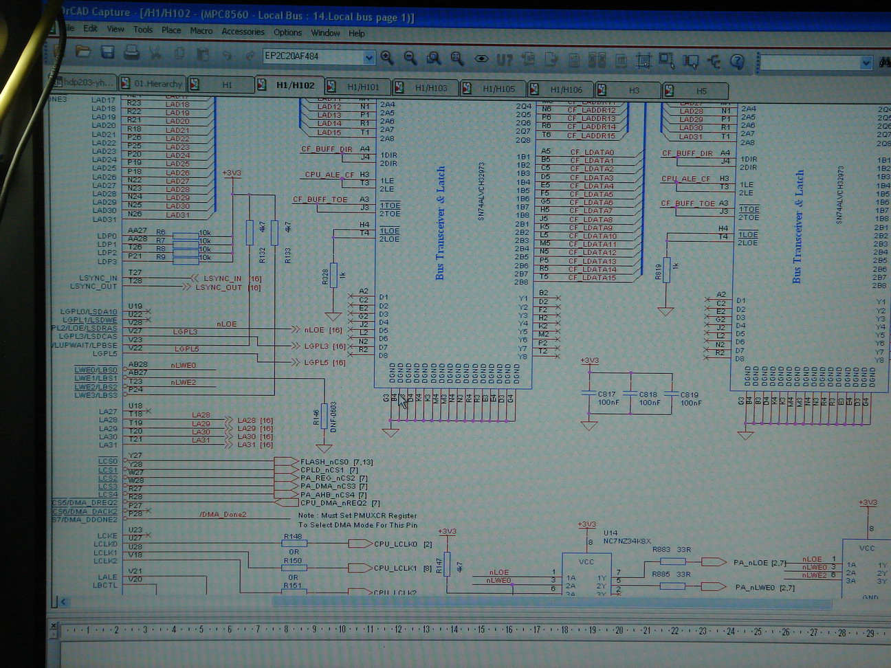
• Altera’s Cyclone II FPGA: 1 x EP2C20AF484
• 256MB DDR SDRAM: 4 x MT46V32M16
• 128MB flash memory: 2 x S29GL512N NOR flash
• Multi-core picoChip DSP processors: 6 x PC203
• Marvell Gigabit Ethernet PHY: 2 x 88E1111-BGA117
• 14 layer PCB
• RTOS: VxWorks
With my own hands, I soldered all electronic components (many hundreds of tiny resistors, capacitors, and chips, except for the big chips like CPU) onto the board. After several months debugging, all chips on the board functioned well and this baseband unit started to work since Apr. 2010.
Some more photos


When hardware was done, I moved on as a software developer, responsible for system level testing and debugging. In the physical layer team, I also contributed a practical tool – an assembly code analyzer, with the purpose of analyzing the picoChip assembly code and plot the diagrams of how the modules/sub-modules are inter-connected. This tool was written in Python. The following figure is an example of what it produces
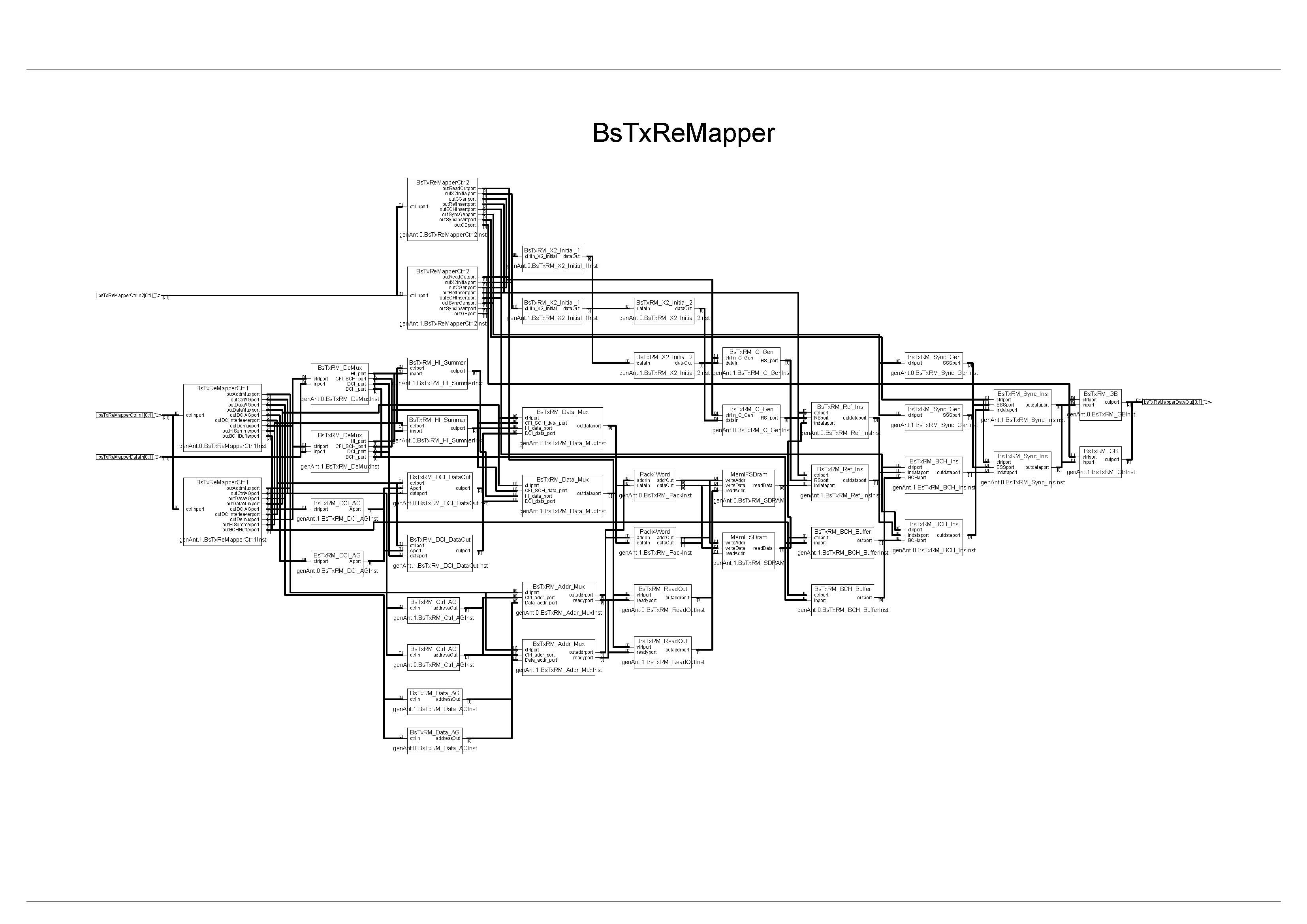
Before this tool was written, my colleagues used to read the assembly source files and draw the diagram in Microsoft Visio. It was a very tedious and time-consuming work, as assembly code is never user-friendly :-). But with my tool, 3 months of work can be done within 3 minutes.
(2) An Intelligent Robot
In 2008, as a third-year undergraduate, I participated in the Intel Cup Undergraduate Electronic Design Contest (ESDC) with my team-mates Mr. Kaiwen Zeng and Mr. Hu Liang.
From March to June, we had been working round the clock on an embedded system project we named “An Assistant for the Handicapped”.
Based on the microprocessor of Intel® Core™2 Duo, we wanted to build a demo of an intelligent wheelchair that had the functionalities of wireless voice control and interaction, automatic obstacle avoidance, object recognition, etc. Everything was designed and built from scratch except for the platform that Intel sponsored. In 3 months, we first constructed a robot structure with very basic tools like pincer, screwdriver, pneumatic drill, wires, and lots of glue. Then a driver circuit was designed in order to enable the robot to move around. Finally we implemented speech recognition and synthesis, image processing and characteristics extraction, and pattern recognition based on the algebraic algorithm for artificial neural network.
There were many days we stayed up all night writing programs or designing circuits. Life in that period was filled with excitements of making progress, as well as sorrows from setback. Finally our system functioned well and we won the first prize of this contest.
Here was how our system looked like
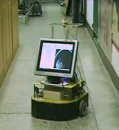
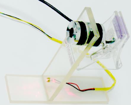
Distance Measurement
The wireless distance measurement module shown below is composed of a web cam, a laser transmitter, and a servo motor. This module is installed on top of the robot and it keeps scanning around to look for obstacles. A laser-beam is projected onto an object in the field of the view of the camera. The pixel coordinates of the laser dot enable us to calculate the actual distance between the camera and the object. When a close obstacle is identified, the system will give an audio warning using Microsoft Text-to-Speech Engines and try to bypass it.
Driver Board
The driver board below controls all motors. It is powered by a big battery. It keeps receiving commands from the upper computer so as to control the moving speed, direction, and which way the web cam should be looking at. 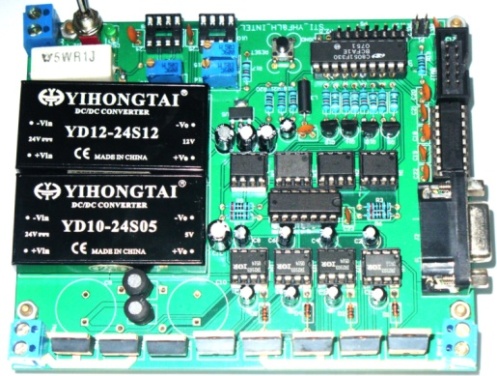
Object Recognition
We realized the pattern recognition using neural network. First of all, we have to extract the object from the background. This is done by measuring the pixel value discontinuity and grey level similarity with OpenCV. Then we pick the characteristics of the known objects, e.g., color, shape, and train the neural network with this information. After the training process, the system can recognize the same objects and tell the user what it sees from its camera. The photo below shows the robot trying to recognize a multimeter I’m holding in my hand.

What I did in this project
• Designed the overall system architecture, all necessary circuit boards, and most of the software.
• Implemented wireless voice control based on Microsoft Speech SDK 5.1.
• Implemented object recognition based on artificial neural network using Delphi.
• Accomplished wireless distance measurement and automatic obstacle avoidance.
